Hybrid microelectronics at Hughes Most of the chips that Hughes Microelectronics was making were of a special
sort called "hybrids." Hybrid chips combine two different kinds of semiconductor
devices on a common substrate. For use in the high-stress world of weaponry,
these hybrid chips are then hermetically sealed in metal or ceramic packages
so they are protected from environmental stress. The circuitry is thereby
isolated in an inert gas atmosphere of helium and nitrogen. This sealing
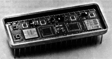
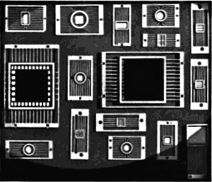
protects the chips from corrosion and other environmental damages. Figure 1 Simple, Un-Sealed Hybrid Microcircuit Figure 2: Examples of Hybrid Packages from the Mid-80’s There were over 70 programs for which Hughes Microelectronics
was manufacturing hybrid chips from 1985 to 1987. The chip for each program
was different. Because of military secrecy as well as company secrecy,
exact specifications of the chips are unavailable. But we provide here
an example of a common hybrid that was likely among those Hughes was manufacturing
at the time: the Analog-to-Digital (A/D) converter. Analog-to-Digital Conversion basics One purpose of Analog-to-Digital conversion (A/D conversion) is to change
a continuously variable analog signal into discrete digital signals that
can serve as input to a computer. An analog signal is a continuously variable physical signal. It can take
many forms: radio wave, cellular phone transmission, radar signal etc.
Usually, in A/D conversion the analog signal takes the form of an electrical
current. An electrical current has a continuously changing voltage, and,
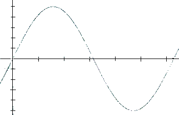
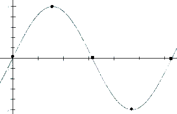
when illustrated, usually takes on a sinusoidal wave form. The complex
sine wave you see here is a combination of several waves, some of which
might be "true" signal and other noise. Figure 3: An example of a sine wave A digital signal is a representation of this wave form as a discrete
set of numerical values. All data that can be 7understood by central processing
units (CPU) are in this discrete binary form. To understand how hybrid
A/D converters function, it is important to note how A/D conversion works
on the circuits. The circuit receives an analog signal (usually an amount
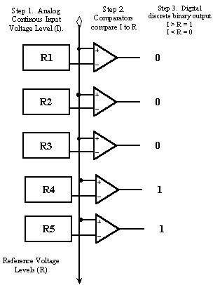
of voltage) and simultaneously compares it to a set of reference voltages. Figure 4: An analog to digital comparator The number of comparators vary by the speed of the hybrid microcircuit
(8-bit, 12-bit, 16-bit etc.). Each comparator is one Least Significant
Bit (LSB) higher than the comparator immediately below it. If the input
voltage level is above the reference voltage, the comparator takes on
a "1" value. If the input voltage is below the reference voltage,
then the comparator remains a "0" value. The output is thus
in binary code as a sequence of zeros and ones that show where the voltage
was at that instant in time. The process described above occurs at a specific
sampling rate measured in Megahertz (megahertz is a million cycles of
electromagnetic currency alternation per second). The input voltage level
continues to change and is regularly sampled a certain amount of times
per second. These discrete samples are then run through the comparators
which produce the binary code. When the binary code switches from 0 to 1, the actual voltage level is
somewhere between the fixed levels of the two comparators. So, the more
comparators there are in the circuit, the smaller the differences between
the fixed voltage levels in the comparators can be. The closer the comparators
fixed levels are, the better the computer’s guess is to the original
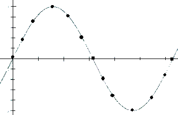
input voltage level. Figure 5: Computer representaation of an analog singal
at a sampling rate of five Figure 6: Computer representaation of an analog singal
at a sampling rate of thirteen In addition, the more frequently the samples are taken, the closer the
digitized representation of the voltage wave is to its actual form. You
can see this easily by thinking of sampling occurring every time there
is a dot in this figure vs. every other time there is a dot. The faster
sampling rate gives a much better picture of the incoming signal. So, increasing the density of sampling and increasing the density of
comparators are the two factors that can make A/D conversion more accurate. So, a hybrid A/D chip has two kinds of technology on it. There has to
be technology to receive, amplify, and relay analog signals. There also
has to be technology to sample the signals and run the samples through
comparators in order to change them to binary code. These complex chips were then sealed in metal or plastic, so that the
extreme variation in battlefield environment would not damage them. If
they leaked when they were shipped form the factory, they could become
damaged more easily in the extremes of battlefield environment. And if
they became damaged (e.g. by heat, or cycling from heat to cold, or by
shock), they could fail in a variety of ways. They might give a wrong
signal or they might give no signal at all. If they gave a wrong signal,
this might not be detected, and the missile might be mis-targeted or the
airplane guidance system might give incorrect readings. In the heat of
battle, or even in training runs, this could have lethal consequences.