Case Materials
Case Navigation
Therac-25 Case
General
Teaching Tools
Case Materials
The material on this page is reprinted from N.G. Leveson, & C.S. Turner. "An Investigation of the Therac-25 Accidents." Computer, Vol. 26, No. 7, July 1993, pp. 18-41. Copyright © 1993 Institute of Electrical and Electronics Engineers. This material is posted here with permission of IEEE. Such permission of the IEEE does not in any way imply IEEE endorsement of any of St. Olaf College's products or services. Internal or personal use of this material is permitted. However, permission to reprint/republish this material for advertising or promotional purposes or for creating new collective works for resale or redistribution must be obtained from the IEEE by sending a blank email message to pubs-permissions@ieee.org. By choosing to view this document, you agree to all provisions of the copyright laws protecting it.
Turntable Positioning
The Therac-25 turntable design is important in understanding the accidents. The upper turntable (see Figure B) is a rotating table, as the name implies. The turntable rotates accessory equipment into the beam path to produce two therapeutic modes: electron mode and photon mode. A third position (called the field-light position) involves no beam at all; it facilitates correct positioning of the patient.
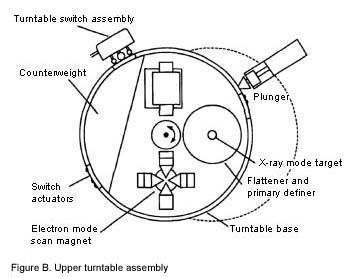
Proper operation of the Therac-25 is heavily dependent on the turntable position; the accessories appropriate to each mode are physically attached to the turntable. The turntable position is monitored by three microswitches corresponding to the three cardinal turntable positions: electron beam, X ray, and field light. These microswitches are attached to the turntable and are engaged by hardware stops at the appropriate positions. The position of the turntable, sent to the computer as a 3-bit binary signal, is based on which of the three microswitches are depressed by the hardware stops.
The raw, highly concentrated accelerator beam is dangerous to living tissue. In electron therapy, the computer controls the beam energy (from 5 to 25 MeV) and current while scanning magnets spread the beam to a safe, therapeutic concentration. These scanning magnets are mounted on the turntable and moved into proper position by the computer. Similarly, an ion chamber to measure electrons is mounted on the turntable and also moved into position by the computer. In addition, operator-mounted electron trimmers can be used to shape the beam if necessary.
For X-ray therapy, only one energy level is available: 25 MeV. Much greater electron-beam current is required for photon mode (some 100 times greater than that for electron therapy)[Rawlinson] to produce comparable output. Such a high dose-rate capability is required because a "beam flattener" is used to produce a uniform treatment field. This flattener, which resembles an inverted ice-cream cone, is a very efficient attenuator. To get a reasonable treatment dose rate out, a very high input dose rate is required. If the machine produces a photon beam with the beam flattener not in position, a high output dose rate results. This is the basic hazard of dual-mode machines: If the turntable is in the wrong position, the beam flattener will not be in place.
In the Therac-25, the computer is responsible for positioning the turntable (and for checking turntable position) so that a target, flattening filter, and X-ray ion chamber are directly in the beam path. With the target in the beam path, electron bombardment produces X-rays. The X-ray beam is shaped by the flattening filter and measured by the X-ray ion chamber.
No accelerator beam is expected in the field-light position. A stainless steel mirror is placed in the beam path and a light simulates the beam. This lets the operator see precisely where the beam will strike the patient and make necessary adjustments before treatment starts. There is no ion chamber in place at this turntable position, since no beam is expected.
Traditionally, electromechanical interlocks have been used on these types of equipment to ensure safety — in this case, to ensure that the turntable and attached equipment are in the correct position when treatment is started. In theTherac-25, software checks were substituted for many traditional hardware interlocks.
Reference: J.A. Rawlinson, "Report on the Therac-25," OCTRF/OCI Physicists Meeting, Kingston, Ont., May 7, 1987.